Looking for a variable power supply for my bench, I stumbled upon this eBay offer: QJE branded 0..15V 0..2A lab power supply for 35 Euros, including shipping and taxes on German eBay (It looks very similar to the Mastech HY1502D on eBay.com, for $55).
I bought it form Komerci.de eBay shop. Ordered Sunday evening, it was sitting on my bench already on Tuesday.
There are some other models that do 0..30V 0..5A but they are more expensive (75-90 Euros) and bigger. As I’m usually not working with voltages over 12V, I thought 15V max would be enough. And for 35Euros more, I can buy a second one and have -15..+15V by putting the supplies in series.
 The supply arrived in a well protected package, being itself in a cardboard, with the instructions and a pair of crocodile-banana wires.
 The front panel has the essentials of a lab power supply: voltage and current knobs, two LEDs indicating the mode (Constant Current – Constant Voltage), two banana sockets (you can unscrew them to connect bare wires) an on/off switch (directly connected to the mains) and two LCD displays, for the voltage and current. A button to switch the supply between the CC and CV mode would be cool, but I guess you can’t ask that much for the price.
The labels are in German (Spannung: Voltage, Strom: Current). As I live in Berlin now, I better get used to it. 🙂
The LCDs have a nice greenish backlight but unfortunately the angles of vision aren’t so great, the digits start to fade if the unit is 40cm on your right or your left side. But they’re ok if you put the unit on a shelf above your head.
 (the backlight is actually easy to see even in daylight)
Another thing I noticed is how hard the knobs were to turn, the low efficiency of the green CV LED, the digital dot being hard to see and the poor LCD refresh rate. More on this later.
Let’s crack it open!
The case is made of metal except the front panel, which is plastic (OK-quality). Everything is held together by eight screws on the sides, plus four on the bottom, two for the front panel and two for the back one.
 The design is quite standard: Control/display PCB on the front, power regulation PCB on the back and multi-tap transformer in the middle. There’s a lot of room left. My unit is the bottom-of-the-line one, so the manufacturer probably uses the same case for the more powerful models. Anyway, more room, less heat!
The cabling is clean, with double-insulated-heat-proofing for the mains (from the mains cable to the fuse and to the transformer, from the mains cable to the front power switch). Unfortunately, no double insulation from the power switch to the transformer.
Also, the transformer secondary cables insulation could have been cleaner.
The screws attaching the transformer, the heat sink and the ground lead have split washers. Good.
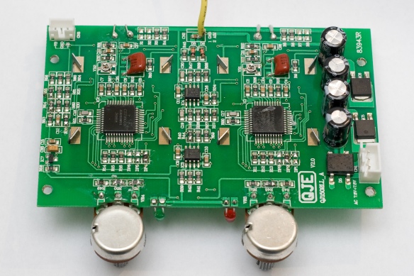
The front PCB is attached to the front panel by four screws and by the potentiometers. It looks like if it was bathed several times in flux. I think it’s the reason why the pots were so hard to turn. I cleaned them with a flux remover and they went back to normal once dry.
 Apart from the flux-terrorism and that yellow wire for output transistor bias being directly soldered on a 1206 capacitor (come on, guys, what’s the point putting connectors for the other cables and doing that for that one wire?!), the PCB design is OK. I like the via-stitches and big planes to help the two voltage regulators dissipate heat.
[Edit: I just noticed there’s a footprint for a connector for the yellow cable, but they decided to solder a capacitor parallel to it and the wire directly on the cap.]
As you can guess, the LCD displays are actually directly driven by the output voltage/current, not by the pots setting. Which means that the unit goes to 16,3V and 2,1A. It also means that what you read on the LCDs is what you’re getting on the output.
This task is done by two identical ICs, the CS7106GN, an obscure piece of silicon, [As Bernhard D. commented: The CS7106GN isn’t really “a obscure piece of silicon, designed and made in china”. It is a chinese copy of the Intersil ICL7106, available since roundabout 1978.] designed and made in china (datasheet here, Chinese-only). It’s basically a voltmeter/LCD driver:
 An interesting thing is the oscillator circuit. I said the LCDs’ refresh rate was poor. In the datasheet, the default capacitor value on OSC3 is 100pF. I replaced it with a 33pF and… Success! the refresh rate is now more than acceptable, without any precision/resolution loss.
I also replaced the green CV led by a more efficient one.
The voltage/current command is entirely analog (the two dual op-amps on the front PCB). It would be interesting to replace the front panel potentiometers by digital encoders commanding two digital potentiometers driven by a microcontroller. Add some USB/Serial capability, two ADC and voilà, you have a remote-controlled lab power supply. Quite tempting!
The output banana connectors are mounted on a PCB with a common mode filter and a protection diode, plus the current shunt. Unfortunately, they’re not bolted but only soldered, as are the output cables:
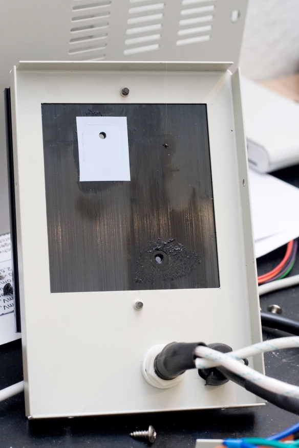
 The voltage/current regulation is made by a TIP3055 power NPN transistor on the other PCB. It’s rated for 90W/70V/15A, so it won’t be screaming with the 15V/2A it’s asked for. The heatsink is also generous (passive cooling only):
The transistor is actually mounted on the other side of the PCB ad directly bolted to the heatsink, with a thermal pad. Simple-but-ok construction.
 (The other hole is to hold the PCB. There’s a plastic spacer between the heatsink and the PCB. The transistor mounting hole is isolated too)
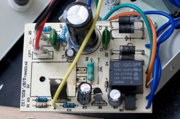
Even if this second PCB looks way cheaper than the front one, the manufacturer make the effort of glueing the filtering cap. The rectifier diodes could be further from the relay due to heat, but I’m not sure they dissipate so much power.
Now, what about the performances?
I compared the LCD readings with the ones on my Fluke 79III (calibrated) multimeter. They’re within 50mV range. The output voltage ripple is below 5mV for all current/voltage combinations.
The unit is within specs, before or after warming up. The relay clicks-in between 4.2V and 4.3V (to switch in the transformer second tap) without any peaks on the output voltage.
The start-up voltage ramp is nice, without any overshooting (and I tried several times, with several voltage settings):
Conclusion:
I must say I’m very surprised by the quality and performance vs. price ratio of this lab power supply. For 35 Euros, I’m not sure you can get even the case from Farnell. Here, you get a very nice 0..15V 0..2A power supply, with digital display, good accuracy and enough for most of the everyday needs. Plus, it begs to be modded!


